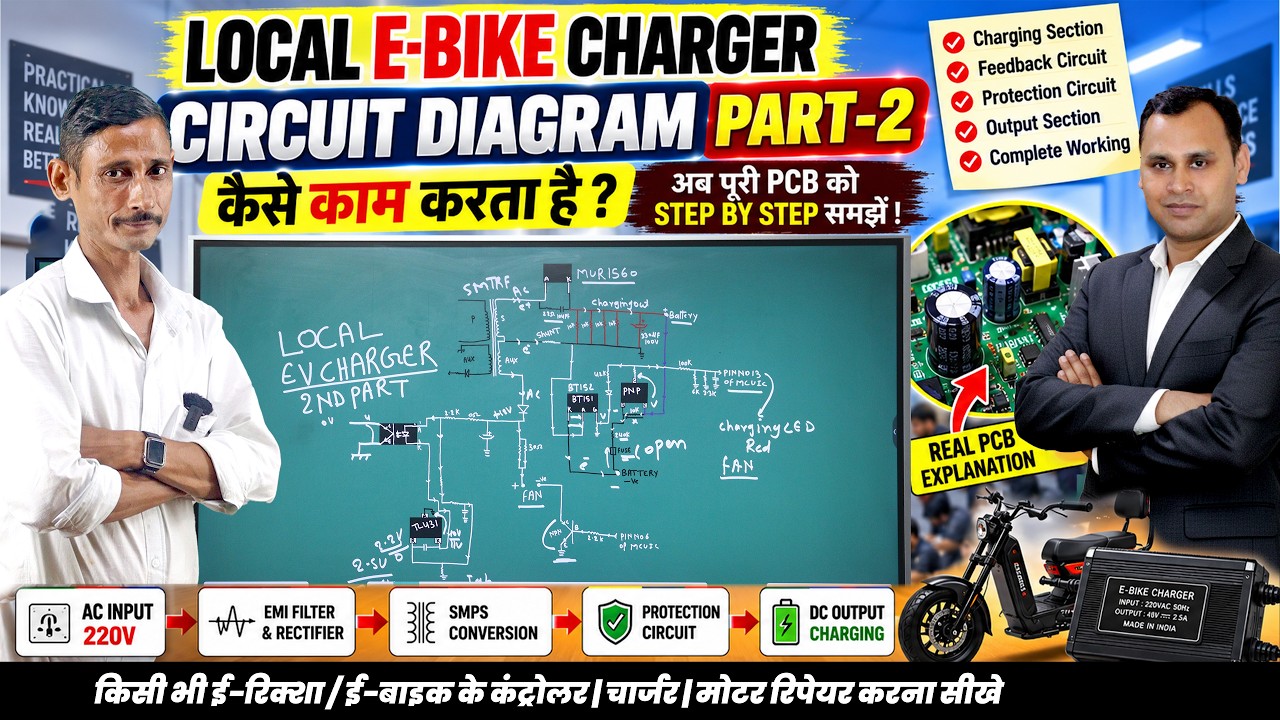
Demystifying EV Tech: Inside the Local EV Charger Protection Circuit and PCB
This article provides an in-depth exploration of EV tech, covering foundational concepts, practical applications, and engineering insights.
Electric vehicles, particularly local E-Bikes and E-Rickshaws, are transforming daily urban transportation. Behind every reliable electric ride is a crucial component that keeps it moving: the EV charger. As sustainable transportation expands, mastering EV tech—especially charger schematics and protection mechanisms—has become an essential skill for technicians, engineers, and enthusiasts looking to repair and maintain these systems effectively.
The Core Mechanics of the Charging Section
The charging section is the heart of any local EV battery charger. Its primary function is to step down high-voltage AC current from standard wall outlets and convert it into a stable, regulated DC output suitable for lithium-ion or lead-acid batteries. Key components within this section include the bridge rectifier, filtering capacitors, and high-frequency switching transformers. Understanding how voltage flows through these stages is essential for identifying common failures, such as blown input fuses or damaged power MOSFETs.
The Critical Role of Protection Circuits
Safety is paramount when dealing with high-current charging systems. Local chargers are often exposed to unstable power grids, making robust protection circuits non-negotiable. Modern EV tech incorporates multi-layered defense mechanisms directly onto the PCB layout:
- Over-Voltage Protection (OVP): Prevents sudden grid voltage spikes from reaching and damaging the battery pack.
- Over-Current Protection (OCP): Limits the flow of electricity to protect internal components from thermal stress.
- Thermal Cutoff: Automatically shuts down operation if internal temperatures exceed safe operating limits.
By analyzing how these protection loops interact with the main control IC, technicians can quickly pinpoint why a charger enters a fault loop or fails to initiate a charging cycle.
Complete PCB Diagnostics and Repair Techniques
A complete evaluation of the printed circuit board (PCB) reveals how low-voltage control signals manage high-power energy pathways. Trace line mapping, checking optocouplers, and signal testing with multimeters are standard diagnostic steps when analyzing board-level failures. Gaining hands-on expertise in local EV tech allows technicians to perform precise component-level repairs, drastically reducing downtime and costs for fleet operators. Whether you are servicing local E-Rickshaws or exploring power electronics, understanding complete PCB functionality is vital in today's electric mobility landscape.


